MENU

Multifunction detection device ST131 PIRANHA-II is intended for detection and localization of special technical means (STM) used for surreptitious obtaining of information, as well as identification of natural and artificial sources of information leakage.

The main types of the STM, for detection of which ST131 is intended, include the following:

The STM with transfer of information by radio channel. Such devices include first of all:

  • Radio microphones including devices with storage and subsequent transfer of information (burst transmitter) and Frequency Hopping Spread Spectrum (FHSS);
  • Telephone radio broadcasting devices.
  • Radio stethoscopes.
  • Wireless video cameras.
  • Mobile telephones and modems of CDMA, GSM, UMTS, DECT standards used without authorization.
  • Devices using digital channels of data transmission of WLAN and BLUETOOTH standards.
  • Radio beacons for object movement tracking.
  • The STM that use AC power, telephone, security and fire alarm lines for information transfer.
  • The STM characterized by information transmission in infra-red range.
  • The STM characterized by transmission of information in ultrasonic frequency range.

SPECIAL SOFTWARE "ST131 ANALYZER- PRO" HIGHLY EXTENDS CAPACITIES OF ST131 FOR ANALYSIS AND PROCESSING OF SIGNALS.


MAIN UNIT

Function Explanations:

Top/Front Side

  1. Receiving-transmitting and control socket in RADIO channel as well as for connection of SHF and infrared detectors.
  2. Socket for connection of transducers operating in ACOUSTIC channel and Magnetic Field Probe
  3. Socket for connection additional Probes
  4. Socket for connection of UHF convertor (RADIO channel) and wire line adapter (WIRE LINE channel)
  5. Valcoder

Bottom/Right Side

  1. Line Out
  2. "3.5" socket for connection of headphones
  3. Volume
  4. Battery compartment covers.
  5. Power ON/OFF
  6. Power supply socket
  7. USB socket

Front Side

  1. "+" and "-" increase/decrease of display brightness level and switching between the bands
  2. "SET" entry in main MENU
  3. "INFO" - entry in the current settings indication of the device
  4. CONTEXT BUTTONS
    Purpose of the context buttons F1 – F5 indicated in the lower line of the display depends on the selected detecting channel and operating mode in this channel.
  5. FUNCTIONAL BUTTONS
    "Full"- switching on the mode FULL RANGE
    "BND" - switching on the mode BAND
    "DMD" - switching on the mode DEMODULATION
    "L" - -switching on the sub-mode SCALE
    "MEA" - access to measuring function
  6. "М" - switching in sub-mode MEMORY
  7. "А" - switching in sub-mode AUTOMATIC ANALYZING
  8. "><" - manual selection of noise level relative to zero value and movement of items in the MENU
  9. ">0<" - automatic selection of noise level relative to zero value
  10. "ENT" -enter (press VALCODER also equal to press Enter)
  11. "0-9, ." - digital keyboard

UHF CONVERTER ST131.UHF

UHF converter is a downconverter of 30 MHz – 4400 MHz frequencies into the frequency range of WIRE LINE channel.

  1. TNC socket
  2. Thread opening ¼”
  3. Switching-on and battery discharge indicator
  4. Indicator intensity of data exchange
  5. Power switch ON/OFF
  6. Battery compartment cover

WIRE LINE ADAPTER ST131.AWL

In ST131AWL constructively combined:

  • Reducing the transformer voltage converter designed to operate in the frequency range of 0.01-30 MHz
  • Low-frequency differential amplifier designed for use in the acoustic frequency range (0.3-15 KHz).
  • Switching unit controlled directly from the main unit and provides the necessary connection of pairs of contacts of the RJ-45. Connection is made as to the most common combinations of pairs and arbitrary, user-defined option.

Connecting to a study done through the line:

  • Connector RJ-45 (3) provide connection to ETHERNET and a telephone line with software, if necessary, pass-through connection.
  • Connectors for connecting test leads (1) that provide connection to other types of wire lines with clips such as "Crocodile".

After selecting a channel "wired" and pressed the button «COMM» of options provided by the commutation of pairs of contacts are connected to the RJ-45 connector.
Combination of "4-5", "3-6", "1-2" and "7-8" are the most likely options are selected and pairs of priority.
Also provides access to the arbitrary choice of pairs (with the exception of the same name), change the polarity and detach from the investigated line.

For attachment to the supplier and holder of the shoulder of the main unit includes a magnet holder and a special slot.

  1. Bananas socket
  2. Ground connector
  3. RJ-45 socket
  4. Indicators of voltage in Line (LINE)
  5. Indicator of overload of signals (OVERLOAD)
  6. Indicator of power supply and link with the main unit (PWR/LINK)

INFRARED PROBE ST131.IR

It is a device integrating receiving photodiode and pre-amplifier.

  1. Infrared probe
  2. Socket
  3. There thread is used for connecting to turning mechanism of the SPECIAL HOLDER.

SPECIAL HOLDER

The HOLDER is intended for facilitation of search of IR transmitting devices those installed at external side of the window in the direction “from the window”.

  1. Handle
  2. Four sections total length of 900 mm.
  3. Turning mechanism

SHF DETECTOR "ST131.SHF"

ST131.SHF consists of the log-periodic antenna and SHF detector-amplifier integrated in one body.

  1. Handle
  2. Log-periodic antenna

MAGNETIC FIELD PROBE (ST131.MF)

ST131.MF consist of the ferrite antenna (FA) placed in the upper part of the detector, pre-amplifier and a handle with integrated battery compartment.

ST131.MF operates in two modes – directly as a magnetic field intensity sensor and as a GRADIOMETER. When using GRADIOMETER mode influence of remote sources of magnetic field is reduced significantly.

  1. Thread opening ¼”
  2. Switching-on and battery discharge indicator
  3. ON/OFF power switch
  4. Battery compartment cover

UHF antenna (ST131.UHF.A)

ST131.UHF.A is a broadband passive antenna.

  1. TNC socket
  2. Аntenna

DETECTING CHANNELS

  1. RADIO
    RF channel
    VHF (0.01-30 MHz)
    UHF (30-4200 MHz)
    SHF (4000-18000 MHz)
  2. WIRE
    WIRE LINE channel (0.01-30 MHz)
    DLA (0.3-15 KHz)
  3. OPTICAL channel
  4. ACOUSTOELECTRIC channel (0.01-125KHz)

CHANNEL "RADIO"

Selective receiving and subsequent processing of radio signals within the range of 10 KHz – 4200 MHz is provided in this channel.

Use of SHF antenna-detector expands frequency range up to 18 GHz.


WIRE LINE CHANNEL

Receiving and processing of the signals transferred by wire line of different purpose (power line, telephone network, computer networks, security and fire alarm lines, etc) with AC or DC voltage up to 250 V.

The main unit is connected to the lines through a wire line adapter (AWL).


OPTICAL CHANNEL

Receiving and processing of the radiations in the optical frequency range is provided in this channel.

Infrared detector ST131.IF is intended for operation in this channel.


ACOUSTIC-ELECTRIC CHANNEL

Receiving, amplifying and analyzing of signals within the frequency range of 10 Hz – 125 kHz is provided in this channel.

Application of one or other types of acoustic transducers depends on the tasks taking into account parameters of this channel.

Ultrasonic signal is converted into audio frequency signal by means of digital heterodyning


The following features has been realized in ST131:

  • THREE MODES: "FULL RANGE", "BAND", "DEMODULATION"
  • THREE SUB-MODES: "SCALE", "AUTOMATIC ANALYZING", "MEMORY"
  • THREE OPTIONS: "OSCILLOGRAPH", "CURSOR MEASUREMENTS", and "DIGIT"

FULL RANGE MODE

This mode is intended in general case for visual estimation of the occupancy level of the selected channel and making decision related to transfer to:

  • Analysis of the specific frequencies using automatic signal detection option “AUTOMATIC ANALYZING”;
  • Detailed investigation of the segments of the range (mode “BAND”);
  • Audio control of signals (mode “DEMODULATION”).

  1. Low frequency of the range
  2. High frequency of the range
  3. Maximal level of the displayed signal
  4. Level and frequency of the maximal signal from the displayed signals
  5. Average noise level value

DETECT” - selection of the option of signal averaging

SCALE” – selection of the displayed dynamic range (Options of 30, 60 and 120 dB are available)

DIFF” - switching on the spectrum subtraction function

DIGITAL” – access to option DIGIT

GAIN” – setting of the input amplifier gain. This function is available in “ACOUSTIC” and "DLA" channels only. Possible values are 0, 6, 14, 20, 26, 34, 40 dB (and others) and “AUTO” (“AUTO” means switching on of automatic gain control (AGC) and is set by default).

The following context buttons are added when pushing the button “MEA”

OSC” – transfer to representation of the signal in time domain (oscilloscope mode)

DRAW” - Selection of type of spectrum display: continuous spectrum or spectrum envelope.

WINDOW” – switching on Hanning window function to improve resolution of the weak signals against the background of strong signals.


MODE "BAND"

This mode is intended for detailed analysis of the signals within selected band. 

  1. Cursor lines of the edges of the analysis band
  2. Cursor line of the central frequency of the analysis band

DEMODULATION MODE

This mode is intended mainly for audio control of the demodulated signal.


SUB - MODES

“SCALE” SUB-MODE

This sub-mode is intended for representation of signal in the form of multi-segment scale with numerical values of the signal level.

SCALE is the most required option in case of location STM.

  1. Calibration of graphic scale
  2. Signal level scale
  3. Values of frequency and signal level

AUTOMATIC ANALYZING SUB-MODE

This sub-mode is intended for automatic separation of the signals, the level of which exceeds the level set by the user.

  1. The value of the marker stop frequency
  2. THRESHOLD level line
  3. Marker
  4. Signal level in marker position.

"TYPE" - - Access to setting an option of the level line.

Choice is possible between a straight line (LINE) and broken line (ENVELOP) repeating smoothed envelop of the spectrum.

"BACK" - Changing direction of MARKER move.


MEMORY SUB-MODE

This sub-mode is intended for storage of the image of the screen in nonvolatile memory of the device. Indication of the stored image is provided in the screen of the device.


OPTIONS

“OSCILLOGRAPH” OPTION

This option is intended for analyzing the signals in time domain.

  1. Value of the time segment per one point of indication
  2. Value of the tuning frequency of the main receiver
  3. Value of the time segment per whole screen of indication
  4. Maximal level of the displayed signal
  5. Root-mean-square value of the signal level.
  6. Value of the signal level from “peak-to-peak”.

"TRIGGER” – activation of the synchronization level line.

TR.TYPE” – access to selection of synchronization conditions

"FREQ" - activation of changing the tuning frequency of the main receiver

"DETECT" - Access to selection of the detector: instant (SAMPLE), peak (PEAK) or average (AVERAGE).


“CURSOR MEASUREMENTS” OPTION

This option provides conducting of absolute and relative measurements of signals by means of the cursor lines.

  1. Value of the central frequency of the band
  2. Main cursor line
  3. Auxiliary cursor line
  4. Value of the level and the frequency of the main cursor lin

BASE” – Selection of measurement of the level of base stations.

AUTO” – Selection of successive automatic scanning of all standards.


SPECIFICATIONS:

DIGITAL SIGNAL PROCESSING MODULE
Simultaneous processing frequency range, MHz
0.01-30
Input signal maximal level, dBm
5
Displayed noise level, dBm
-100 (РС mode),
-90 (main unit ST131)
Resolution ADC, bit 14
Number of FFT points
32768 (PC mode)
512 (main unit ST 131)
Filters sizes, МHz
0.001-6.8 MHz
Demodulation types
АМ, FM, SSB, TV (АМ)
Identified data transfer standards
GSM, WLAN, BLUETOOTH, DECT, UMTS, WiMAX
Detectors
Root-mean-square,
peak,
quasi-peak
 
RADIO CHANNEL. UHF CONVERTER
Frequency range, MHz
30-4300
Displayed noise level
Within the whole bandwidth, dBm
Within DDC bandwidth 1 kHz, dBm

-67
-110
Input signal maximal level, dBm
5
Value of DDC bandwidth, MHz 224, 112, 54, 56, 28, 6.8, 2.5, 0.63, 0.15, 0.075, 0.04, 0.001 and 0.0005
Sweep speed, GHz/sec, at least
10
 
RADIO CHANNEL. SHF CONVERTER
Frequency range, GHz
4-18
Threshold sensitivity, W/cm2
2x10⁻¹⁰
Dynamic range, dB
45
Type of antenna
log-periodic
Antenna beamwidth, degrees
60-90
 
WIRE LINE CHANNEL
Frequency range 1 (CH1), MHz
0.01-30
Frequency range 2 (CH3), KHz 0.3-15
Common-mode interference attenuation factor, dB 60
Absolute maximum input level, V
250
 
OPTICAL CHANNEL
Spectral range, nm
770-1600 (560-1100)
Detecting frequency range, KHz
0.1-1500
Dynamic range, dB
55
 
ACOUSTIC CHANNEL
Frequency range, KHz
0.01-125
Dynamic range, dB
90
Input signal maximum level, V
1

DELIVERY OPTIONS:

BASIC SET
Main unit
1
UHF converter (ST131.UHF)
1
Broadband UHF antenna - ST131.UHF.A
1
Wire line adapter (ST131.AWL)
1
Leads
1
Main unit supporting block
1
Main unit shoulder holder
1
Headphones
1
Tripod
1
Power supply unit
2
AA batteries
8
Mini-disc with software
1
User manual
1


SUPLEMENTARY SET
SHF DETECTOR ST131.SHF
1
IR probe ST131.IR
1
Magnetic field probe ST131.MF
1


ATTENTION! ST-033 is discontinued and replaced with more advanced device ST-131 Piranha II

Please follow this link to ST-131 Piranha II

--------------

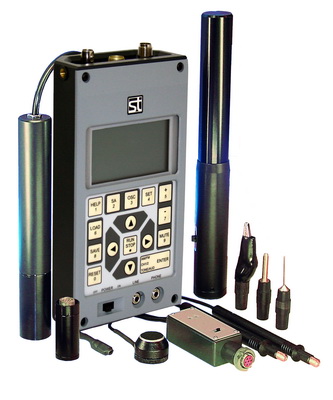
The ST 033 "PIRANHA" multifunctional countersurveillance device is designed for detection and localization of special technical means (STM) used for secret acquisition of information, for detection of natural and artificially created channels for leakage of information.

The ST033 consists of the Main Control and Indication Unit, and a set of Transducers, and is capable of operating in the following modes:

  1. HF detector/frequency meter
  2. SHF detector (with ST03.SHF)
  3. conducting line analyser;
  4. infrared detector;
  5. low frequency magnetic field detector;
  6. acoustic transducer.
  7. low frequency differential amplifier (with ST03DA).

The device allows to process the received low frequency signals in either oscilloscope mode, or spectrum analyser mode with a digital representation of data. Its non-volatile memory can store up to 99 screen images.

Special software is allows:

  • the transfer of information from ST 033P's display on to the PC.
  • the creation of a database of graphic and audio files, that are being generated in the process of operation with ST 033P in real time, or are retrieved from ST 033P's non-volatile memory.
  • firmware upgrade via internet

Control of the scanning receiver (AOR8000, 8200, 5000).

The scanning receiver can be controlled while the instrument operates in the HF detector/frequency meter mode, and conductive line scanning analyser mode. The action is based on tuning the receiving frequency of the scanning receiver, to match the frequency of the signal received.

ST 033 is a portable unit. For handling and storage a special bag is used.

Specifications
Radio frequency detector-frequency meter
Operating frequency range, MHz 30-2500
Sensitivity at input, mV <1 (30MHz-1000MHz)
<4 (1000MHz-1800MHz)
<8 (1800MHz-2000MHz)
Dynamic range, dB 60
Frequency meter sensitivity, mV <15
Frequency measurements accuracy, MHz ± 0.01
   
SHF detector  
Frequency range, GHz 2.5-8
Threshold sensitivity, W/cm² 2.5x10⁻¹⁰
Dynamic range, dB 32
Type of antenna Log-periodic
Antenna beamwidth, degrees 60-90
   
Conductive wire lines scanning analyzer
Scanning range, MHz 0.01-15
Sensitivity for signal/noise ratio 10 dB, mV <0.5
Scanning step, kHz 5(1)
Scanning speed, kHz/s 50-1500
Bandwidth, kHz 10
Selectivity as per neighboring channel, dB 30
Demodulation types AM, FM
Maximum allowable input voltage, V 600
 
Infrared channel
Spectral range, nm 770-1000
Threshold sensitivity, W/Hz1/2 10-13
Angle of sight, degrees 30
Bandwidth of detection, MHz 3
 
Magnetic fields detector
Frequency range, kHz 0.3-10
Threshold sensitivity, A/(m x Hz2) 10-5
Gain, dB 22±1
   
Acoustic channel
Frequency range, kHz 0.3-8
Sensitivity, mV/Pa >5
 
Oscilloscope and spectrum analyzer
Frequency range, kHz 0.01-22
Sensitivity at the input, mV <10
Inaccuracy of measuring, % (of the upper limit) 1
Oscillogram output speed, s 0.2
Spectrogram output speed, s 0.3
 
Power
Power supply (DC), V (4 batteries, AA type)
 100-240 V
Maximum consumed current, mA 300
Consumed current in operating mode, mA 150
 
Dimensions and weight
Main processing unit: overall dimensions, mm 180х97х47
Main processing unit: weight, kg 0.8
Complete set: overall dimensions, mm 350х310х160
Complete set: weight, kg not exceeding 5
 
The complete set
1. The main control processing and indication unit 1
2. Radio frequency antenna 1
3. SHF detector ST03 1
4. Adapter for conductive wire lines analyzer 1
5. Differential low frequency amplifier (ST033.DA)* optional
6. Magnetic sensor 1
7. Infrared sensor 1
8. Acoustic sensor 1
9. Control device "ST03.TEST"* optional
10. Telescopic antenna 1
11. "Needle","220"and "Alligator" type extensions 2X3
12. Headphones 1
13. Shoulder belt for the main unit, with a pocket for sensors 1
14. Main unit support 1
15. Power supply unit 1
16. AA type batteries 4
17. User Manual 1
ST-031M
ST-031M Multifunction TSCM device
ST-031M
ST-031M
ST-031M
Case
ST-031M
ST-031M Multifunction TSCM device
ST-031M
ST-031M
ST-031M
ST-031M
previous arrowprevious arrow
next arrownext arrow
ST-031M
ST-031M Multifunction TSCM device
ST-031M
ST-031M
ST-031M
ST-031M
previous arrow
next arrow
 
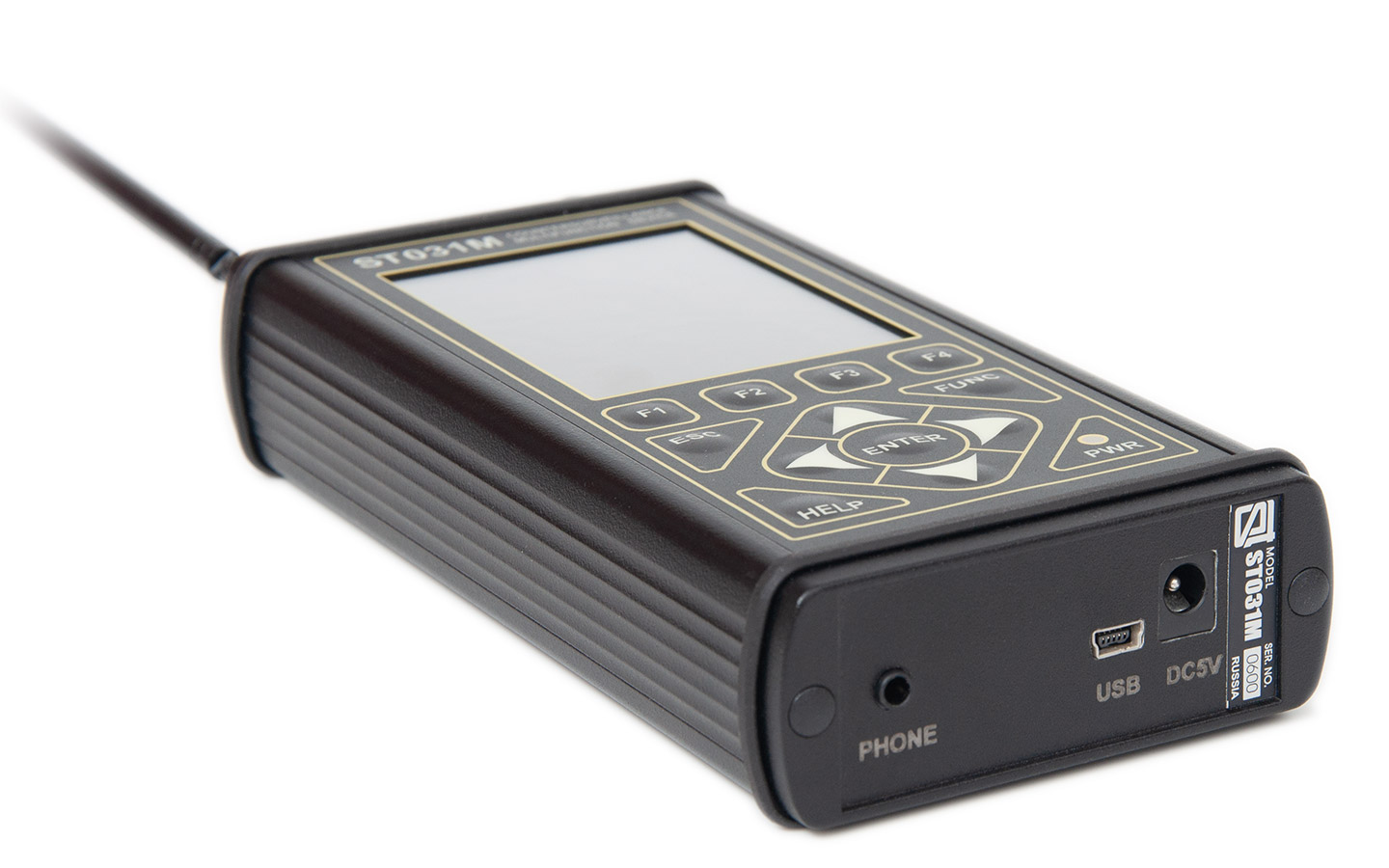
Piranha ST-031M is a new generation multifunctional search device for detection and localization Special Technical Means of Obtaining Secret Information (STMOSI) and for solving other information protection tasks related to information protection technical measures effectiveness evaluation. ST031M is logic continuation of the well-known multipurpose devices "Piranha" series. The device has the best “cost-capabilities” ratio in the entire class of such a devices.
 
ST-031M Multifunctional Search Device allows us to discover the facts and determine the location of the radio-emitting devices and devices transmitting information over 220V mains, which create a potentially dangerous information leakage channel. These means primarily include the following:
  • Radio microphones;
  • Telephone transmitters;
  • Radio-stethoscopes;
  • Concealed video cameras equipped with a radio channel for transmission of information;
  • Technical means or systems for spatial radio frequency radiation;
  • Beacons of the systems used for moving objects monitoring (e.g. people, transportation means, goods etc.);
  • Unauthorized radio stations, radio handsets, and also telephones with radio-extension;
  • Radio modems and digital wireless access systems.

Features:

  • ST-031M construction, delivery set, technical features and characteristics allow detection of wide range of mostly dangerous STMOSI devices.
  • Technical possibilities of the device as whole and additional devices allows to find almost all of the most dangerous physical fields used by STMOSI.
  • Independence from external power supplies allow autonomous operation and removes limitation of device use.
  • The device allows to investigate the received signal in spectrum analyzer and oscilloscope mode.
  • The device has a mode of identification for standard digital data transmission channels (GSM, DECT, BLUETOOTH, WIFI and etc.).
  • Connection to PC allows controlling and information logging directly from computer screen.
  • Color-LCD display.
  • The interface of ST 031M is simple and intuitive. Its design took long-term experience of operation of our previous models into account.

Signals detection capabilities:

  • ST-031M "Piranha" consists of three detection channels, each of which is designed to search for signals in a particular frequency range. Set of antennas, sensors and adapters allows to adapt the device to process search for a variety of eavesdropping devices and information leakage of natural origin.
  • Identification of digital protocols. Device is able to distinguish between signals from the base station and signals from cellular phones.
  • Custom, user preset, bands.

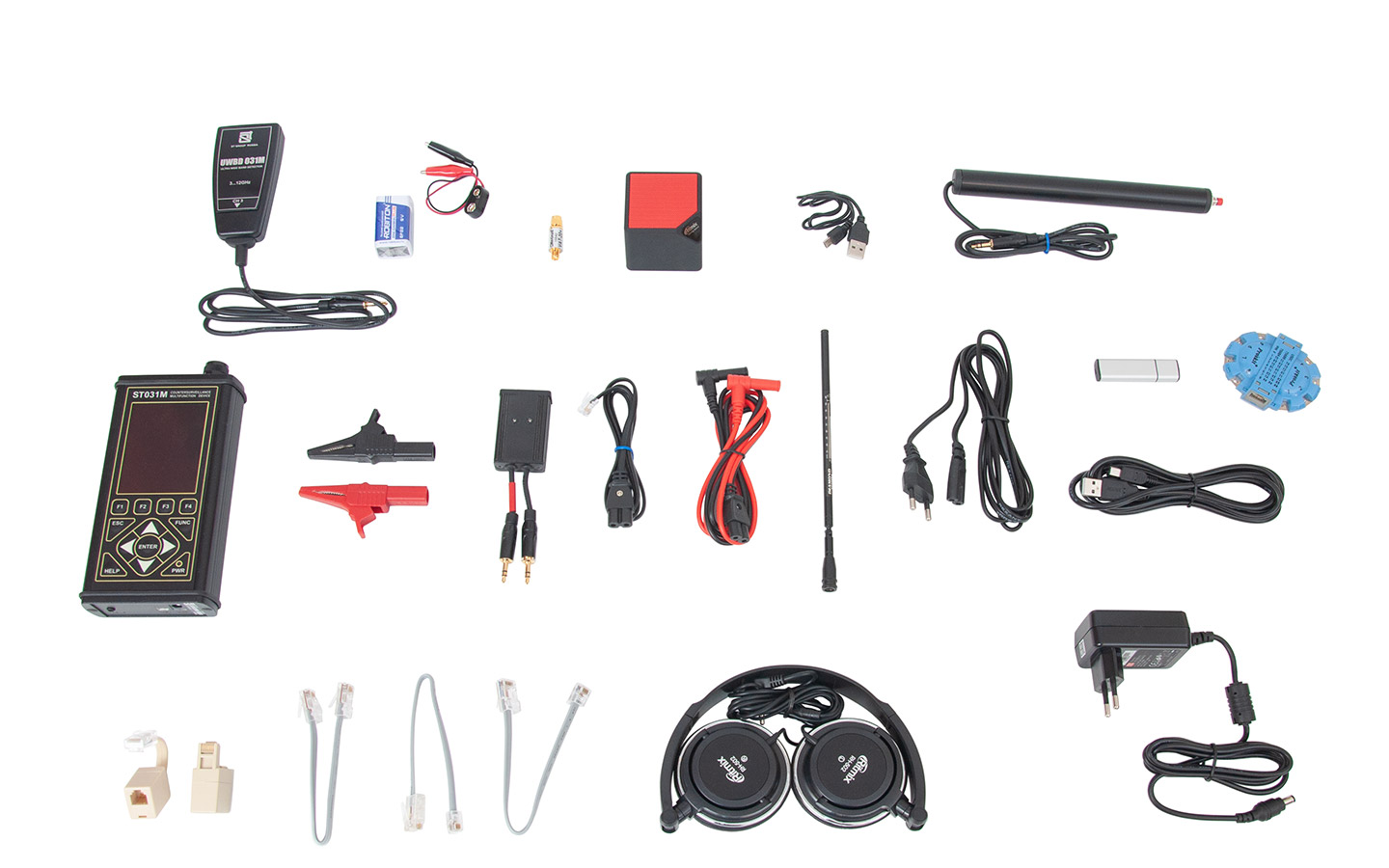
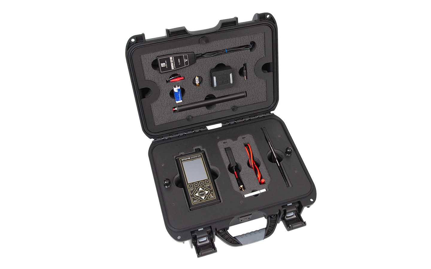
Delivery set:

  1. Ultrahigh frequency sensor (UWBD031M).
  2. Conductive wire lines differential generator
  3. Battery (for conductive wire lines differential generator) .
  4. Attenuator.
  5. Test sound emitting device.
  6. Connecting cable of sound emitting device.
  7. Induction converter (Magnetic field sensor).
  8. Main controlling, processing and displaying unit.
  9. "Crocodile" type clamps (2 pcs).
  10. Multipurpose adapter for checking wire lines - BWLC031M.
  11. Cable to connect BWLC031M adapter to telephone lines.
  12. Multipurpose cable to connect BWLC031M adapter to wire lines.
  13. High-frequency telescopic antenna.
  14. Cable to connect BWLC031M adapter to electricity sockets for scanning receiver CH2.
  15. Flash drive with software.
  16. Cable to connect to a PC.
  17. Adapter to connect BWLC031M adapter to the multi-wire cables.
  18. Telephone adapters (2 pieces).
  19. Cable connectors type RG45: 8?4; 8?6; 8?8.
  20. Headphones.
  21. Charger.
  22. Carrying case.
  23. User manual and warranty certificate.

Technical characteristics:

Main unit
Channel 1. Selective HF detector
Input impedance, Ohm 50
Operating frequency range, Mhz 140…4420
Bandwidth, Mhz 1-40
Scanning speed, Ghz/s 40
Irregularity of the frequency response, dB ±5
Minimally detectable signal in the automatic mode, dBm
≤ –65
Dynamic range, dB 50
Demodulation modes AM, wideband FM
Channel 2. Scanning receiver
Input impedance (symmetrical), Ohm 600
Operating frequency range, Mhz 0,05…140
Bandwidth, Khz 40
Scanning speed, Mhz/s
35
Irregularity of the frequency response, dB ±5
Minimally detectable signal in the automatic mode, dBuV 25
Dynamic range (without attenuator), dB 65
Attenuation of built-in attenuator, dB 20
Demodulation mode AM, FM
Channel 3. Low-frequency amplifier
Input impedance, kOhm 100
Operating frequency range, Khz 0,025…100
Irregularity of the frequency response, dB ±1
Integral voltage level of noise, dBuV -109
Amplification ratio, dB 12, 24, 36, 48
Sound path
Frequency range, Hz 300…9000
Volume regulation range, dB -50…+20
Max power output in the output “PHONE”, mW 150
Display
Type of display LCD-TFT 3,2”
Resolution 240x320
Colour quantity 65000
Power supply
Lithium-polymer battery with a voltage, V 3.7
Power consumption, W 1,2…2,5
Continuous operating time at max. power consumption, hours >7
Time to charge a fully discharged battery, hours 7
Weight, dimensions
Dimensions of the main unit (length, width, height), mm 175x83x36
Weight of the main unit, kg 0,430
Dimensions of the case (length, width, height), mm 390x310x170
Full weight of the set in case, kg 3,8
Multipurpose adapter for checking wire lines BWLC031M
Maximal allowed voltage in the power line, V 300 AC, DC
Insulation resistance for "input / output", mOhm >10
In “Channel 2” mode
Input impedance, Ohm 100
Operating frequency range, Khz 0,05…140
Maximal allowed signal level, dBV -10
In “Channel 3” mode
Input impedance (symmetrical), Ohm 27
Operating frequency range, Khz 0,150…100
Maximal allowed signal level, dBV 10
In-phase signal attenuation, db >65
Ultrahigh frequency sensor
Operating frequency range, Ghz 3…12
Threshold sensitivity, W/cm2 2*10-10
Polarization Linear
Directional angle 60…90
Dimensions (length, width, height), mm 100x45x25
Weight, kg 0,07
Cable length 0,95
Induction converter (Magnetic field sensor)
Operating frequency range, Khz 0,07…100
Measuring range of the magnetic field, nT 0,5…2000
Attenuation of a homogeneous field in the diff. mode, dB >30
Dimensions (length, diameter), mm 205x20
Weight, kg 0,11
Cable length, m 0.95
Test sound emitting device
Flash card slot  microSD
Audio file format  MP3
Speaker  RMS 3W, 150…18000 Hz
Power supply  Li-Ion battery 600 mAh
Continuous operating time, h  3
Charging time, h  3

Latest news:

  • iProtect-1217-detector.jpg
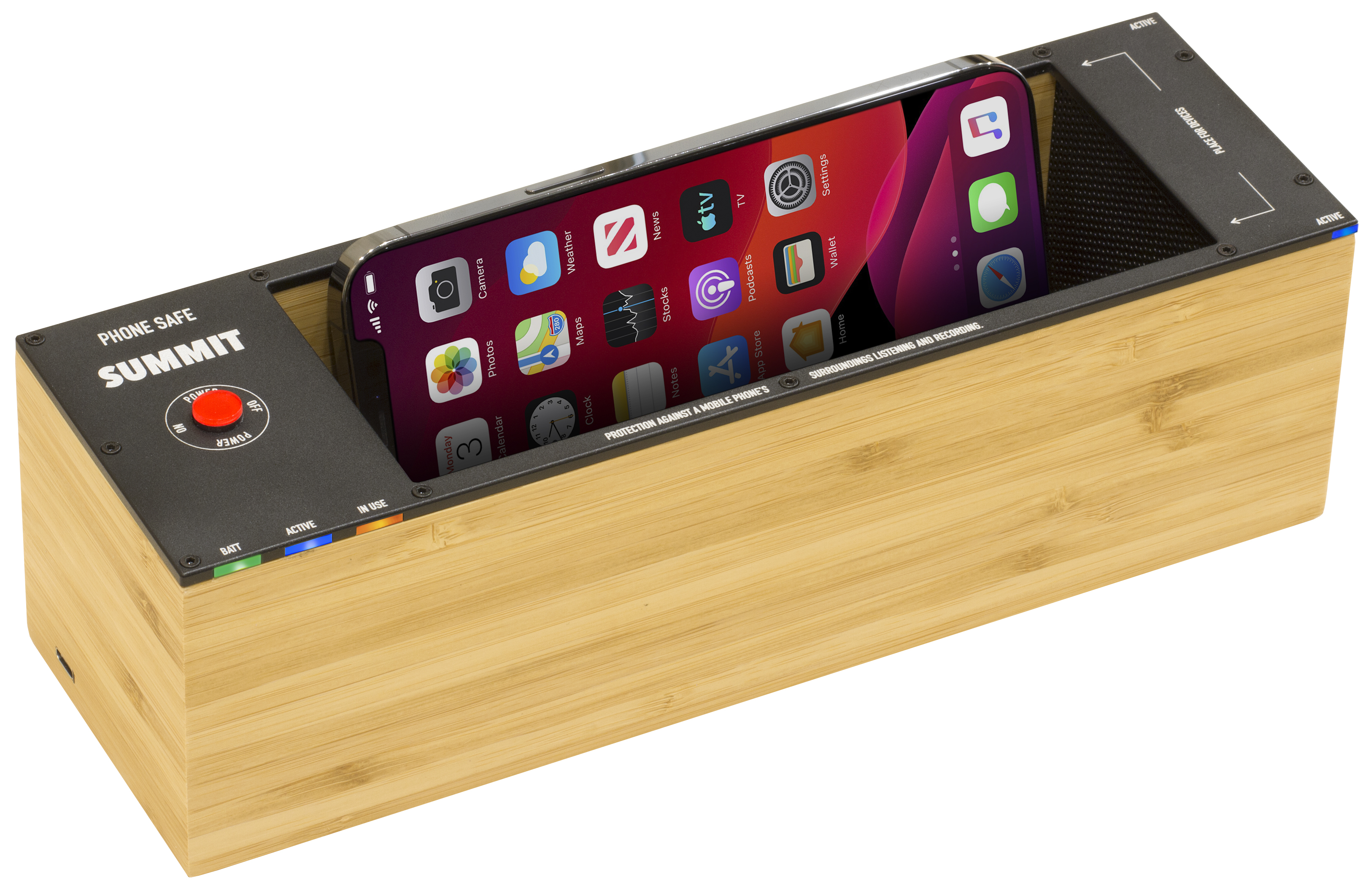
    Phone Safe Summit
    Date: 2024-07-05
    One of the potential leakage channels is the phone's microphone being able to pick up surrounding acoustics with a high sensitivity. The PHONE SAFE SUMMIT has been developed by information security professionals to protect against this exact type of threat.
    Link to complete description: Phone-Safe-Summit description
     

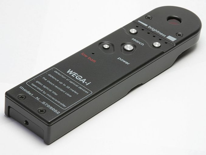
  • WEGAi
    WEGAi
    Date: 2024-06-28
    WEGAi - pinhole camera detector has been added to our website
    Link to complete description: WEGAi description
     

  • iProtect-1217-detector.jpg
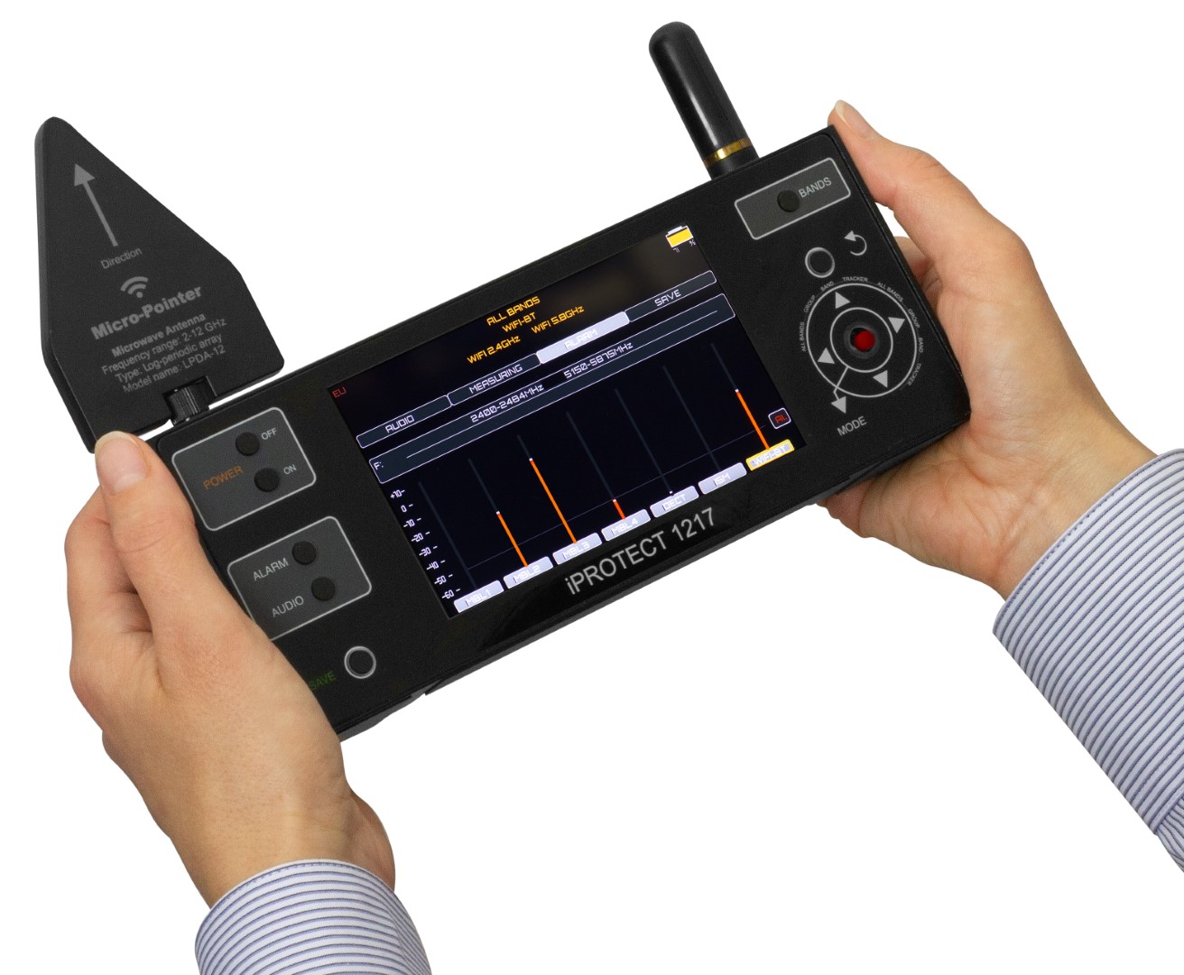
    iProtect-1217
    Date: 2024-06-28
    iProtect-1217 - detect GSM, 3G, 4G/LTE and 5G
    Link to complete description: iProtect-1217 description

  • iProtect-1217-detector.jpg
    Protect-1207i
    Date: 2024-06-28
    Protect-1207i - detect GSM, 3Gand 4G/LTE
    Link to complete description: Protect-1207i description

  • Website Update
    Website Maintenance
    Date: 2024-05-22
    Website is under maintenance, contact forms might not work. Please write all your inquiries directly by email This email address is being protected from spambots. You need JavaScript enabled to view it.

  • Milopol TSCM
    Milipol 2017
    Date: 2017-11-15
    We are proud to announce we are participating at the exhibition MILIPOL 2017 Paris 21-24th of November
    Our booth number A061 
    Most important products will be demonstrated including:
    • ST-121 test signal generator for TSCM training.
    • ST-167 with WiFi module and relay contacts.
    • ST-154 multizone spectrum monitoring.
    • ST-171 RF jammer detector.
    • ST-131 Piranha II multifunction TSCM device.
    • Lornet and Cayman Series NLJD.
    • CGU-OCD20 laser camera detector.
    • Voron, Optic-2 camera detectors.
    • And other equipment
     

  • ST-121 TSCM training test signal generator
    GSM, 3G, 4G and GPS jammer detector.
    Date: 2017-10-25
    ST-171 is intended to detect GSM, 3G, 4G and GPS jammers for theft prevention in parking lots, offices and private territories. Detection of cellular or GPS receivers jammers in cars moving along a highway, street etc.
    Link to complete description: ST-171 description
     

  • ST-121 TSCM training test signal generator
    Test signal simulator for TSCM training. ST-121
    Date: 2017-10-10
    Device is intended for simulation of test signal and is a handy tool to use in TSCM training or laboratory measurements.
    Signal simulator is intended to imitate operation of most common transmitting devices, such as:
    • RF transmitters in frequency range 100-6000 MHz
      Modulations: AM, FM, Sinusoidal, DSSS, FHSS, PULSE;
    • Information transmission over 220V mains lines;
    • Transmission over low-voltage, phone lines;
    • Optic channel, IR emission;
    • Ultrasonic sound;
    Link to complete description: ST-121 description
     

  • ST-154 multizone remote RF spectrum monitoring device
    ST-154 Distributed multizone RF monitoring
    Date: 2017-09-01
    ST-154 is a distributed, multizone RF spectrum monitoring system. Remote modules are deployed around the premises and provide 24/7 real-time RF spectrum monitoring in 25-6000 MHz frequency range. Most common wireless and cellular communication signals are identified. Events recording, review and filtering are possible. System setting are highly customisable.
    Spectrum information and potentially dangerous events are transmitted in real time by Ethernet or WiFi to central monitoring station. Up to 128 remote monitoring points. Signal localisation is possible by comparing real-time data from several remote ST-154 monitoring modules.
    Link to complete description: ST-154 description
     

  • ST-300-Spider-wire-lines-analyser
    SPIDER cable lines analyser
    Date: 2017-09-01
    SPIDER wire lines analyser can detect tapping and information gathering by surveillance devices connected to landline phone lines, 220V mains, low voltage lines and etc.
    Link to complete description: SPIDER
     

  • OPTICAL Camera Lenses Detector
    OPTICAL Camera Detector
    Date: 2017-08-01
    Optic-2 binocular camera detector with 6.5x magnification, dioptric adjustment, greed and red LED diodes. Available in stock.
    Complete information link: Optic-2 camera detector
     

  • Cayman 401 403 detector
    Cayman 403 - non linear junction detector
    Date: 2016-08-01
    New model of non linear junction detector Cayman 401 also known as Cayman 403 is available in stock.
    Complete information link: CAYMAN 401 (403)
     

  • Cayman 400 402
    Cayman 402 - non linear junction detector
    Date: 2016-08-01
    New model of Cayman 400 also known as Cayman 402 has following advantages:
    • Improved antenna constructions ensures higher selectivity of the device.
    • Decreased weight and size.
    • Simplified control and indication system.
    • New type of batteries - easy to find and purchase in the market 3,7 volt (type 18650).
    • More ergonomic design.
    Complete information: CAYMAN 400 (402)