ST-121 Test Signal Generator TSCM


ST-121 test signals generator description:
Signal generator ST-121 is intended to imitate operation of most common bugging devices, such as:
- RF transmitters;
- Information transmission over 220V mains lines;
- Transmission over wires;
- Optical channel;
- Ultrasonic;
Device ST-121 can also imitate electromagnetic interference and noise from electronic devices such as solid-state audio recorders and cell phones (TEMPEST applications).
ST-121 application areas:
- Training personnel responsible for TSCM activities;
- Testing TSCM equipment functionality;
- Laboratory measurements;
ST-121 key features:
- Complete RF signal generator in a wide frequency range: 0.01-20MHz and 100-6000 MHz.
- Self-powered from internal rechargeable batteries.
- Stand-alone operation. PC is not required.
- Small dimensions, highly portable.
- Robust design.
ST-121 signals generation capabilities:
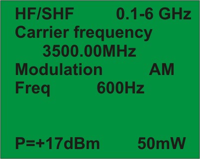
- Radio signals with user-defined frequency in 100 – 6000 MHz range. Operator controlled variable output power. AM, FM, FHSS, DSSS and PULSE modulated signals.
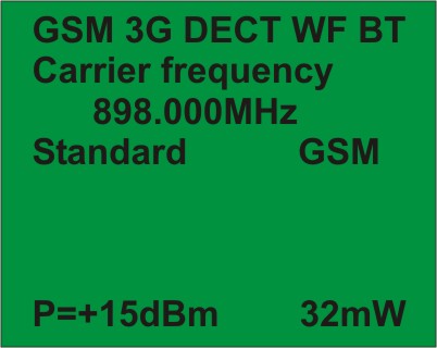
- Signals imitating data transmission standards (GSM, DECT, BLUETOOTH и WLAN).
- HF and LF signals in the 220V main power lines and RJ-45 low current lines. AM, FM and PWM modulations.
- IR signal with LF signal modulation and a possibility to select a subcarrier frequency.
- Sound and ultrasound signals with user-defined frequencies or a selected octave and third-octave filter frequencies. (Direct connection of speakers to the ST121 output socket is available).
- Low-frequency magnetic field.
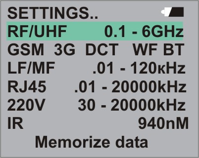
Examples of few ST-121 user interface screens:
ST-121 technical characteristics:
| "HF/SHF" socket | |
| Frequency range, MHz | 100-6000 |
| Frequency-tuning step, kHz | 10, 100, 1000, 10000, 100000 |
| Signal level, dBm | from -42 to +14* |
|
Stray harmonics, dBm
@ 100-200MHz
@ 200-700, 1100-1500MHz
@ 800-1000, 1600-6000MHz
|
-15
-45
-30
|
| Signal | Sinusoidal, DSSS, FHSS, PULSE |
| Modulation | AM, FM |
| Data transmission standards imitation | GSM, 3G, DECT, WLAN, BLUETOOTH |
| Modulation frequencies, kHz |
0.5; 1; 5; 15;
|
| АМ depth, % | 70 |
| FM Deviation, kHz | 5, 20, 100, 300, 600 |
| Nonlinear distortion of modulating signal, no more than, % | 15 |
| Bandwidth of Hopping, MHz | 1, 6, 10, 20, 50, 100 |
| Number of Hopping Channels | 25, 50, 125, 250 |
| FHSS frequency of hopping, Hz | 1, 2, 4, 8 |
| DSSS bandwidth, MHz | 0.3; 0.5; 1; 2; 4; |
| PULSE Signal transmission time, sec | 0.0001 - 99 |
| PULSE Signal accumulation time, sec | 0.01 - 5999 |
| * Variation range depends on signal frequency and selected standard | |
| "RJ-45" socket | |
| Frequency range, kHz | 0.01-20000 |
| Maximum signal amplitude, V | 3.5 |
| Modulation | AM, FM, PWM |
| Modulation frequency, kHz | 0.5, 1, 1, 5, 15 |
| АМ depth, % | 15 |
| FM Deviation, kHz | 5, 20, 100, 300 |
| The frequency of the PWM signal, Hz | 1, 10, 40, 100 |
| Duty cycle | 1, 5, 10 |
| "220V" mains socket | |
| Frequency range, kHz | 30-20000 |
| Maximum signal amplitude, V | 3.5 |
| Maximum input voltage, V | 380 |
| Modulation | FM, DSSS |
| Modulation frequency, kHz | 0.5, 1, 1, 5, 15 |
| Distortion, kHz | 5, 20, 100, 300 |
| PRF, Hz | 1, 10, 40, 100 |
| Duty cycle | 1, 5, 10 |
| “IR” emitter | |
| Wave length, nm | 940 |
| Subcarrier frequency range, kHz | 0.01- 5000 |
| Stray harmonics, dBm | 30 |
| Output power, mW | 0.5 |
| Modulation | AM, FM, DSSS |
| Modulation frequency, kHz | 0.5, 1, 5, 10, 15 |
| АМ depth, % | 15 |
| Distortion, kHz | 5, 20, 100, 300 |
| PRF, Hz | 1, 10, 40 and 100 |
| Duty cycle | 1, 5, 10 |
| "LF" socket | |
| Socket | Symmetrical |
| Frequency range, kHz | 0.01-120 |
| Maximum output power, W | 0.7 (power supply), 0.3 (internal battery) |
| Power levels, % | 7.5; 14; 20; 32; 50; 65; 80; 100; |
| Impedance, Ω | 8 |
| Frequency-tuning step, kHz | 1, 10, 100, 1000 |
| Octave filters frequency values, Hz | 32, 63, 125, 250, 500, 1000, 2000, 4000, 6000, 16000, 31500 63000 |
| Third octave filters frequency values, Hz | 32, 40, 50, 63, 80, 100, 125, 160, 200, 250, 315, 400, 500, 630, 800, 1000, 1250, 1600, 2000, 2500, 3150, 4000, 5000, 6300, 8000, 10000, 12500, 16000, 20000, 25000, 31500, 40000, 50000, 63000, 80000, 100000, |
| Nonlinear distortion, no more than, % | 1 |
| Modulation | AM, FM, DSSS |
| Modulation frequency, kHz | 0.5, 1, 1, 5, 15 |
| АМ depth, % | 15 |
| Distortion, kHz | 5, 20, 100, 300 |
| PRF, Hz | 1, 20 |
| Duty cycle | 1, 5, 10 |
| Magnetic field emitter «MF» | |
|
Equivalent magnetic moment of magnetic field source with frequency 1kHz, A*m2
@ 100% of power
@ 7.5% of power
|
2*10-4
2*10-5
|
| Power | |
| Power supply | Li-Polymer battery, 2.2A/h or 220V power supply |
| Max current consumption, mA | 500 |
| Main module dimensions, mm | 110x60x28 |